Pentagon Mood Lamp: Five Colours, an ESP32 and Its Own Remote
A laser-cut pentagon lantern with one colour per side. An ESP32-C3 dims five 12 V COB LEDs through 2N2222 transistors, controlled from a five-button remote you build yourself or from your phone. Cut files, firmware and an assembly guide included.
Project Overview
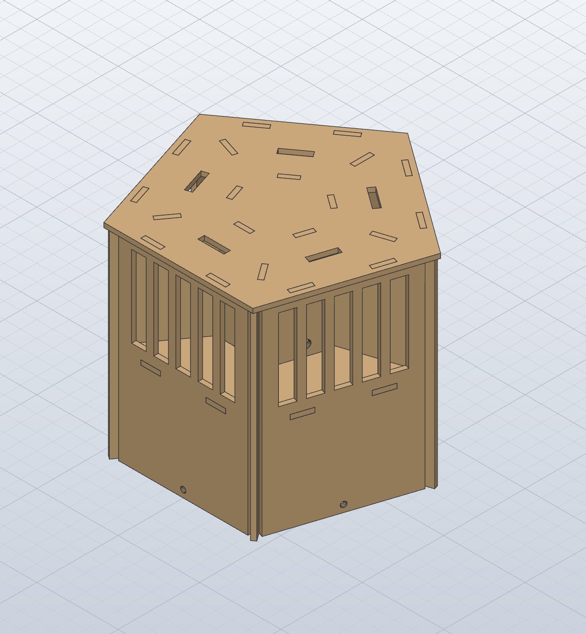
A sharp-cornered pentagon lantern with one colour per side. Five 12 V COB LEDs sit in five separate rooms behind slotted plywood walls, so each side glows its own colour: blue, yellow, orange, green and pink.
An ESP32 switches and dims each colour through its own 2N2222 transistor. You control it from a five-button remote you build yourself or from a page on your phone, with no app and no router.
Designed and checked, not built yet
Every part and fit was checked by script, and the pictures are 3D renders. One LED channel has been tested on the bench with the real firmware; the full lamp has not been cut or assembled yet. Bought-part sizes are typical values: measure yours and cut the fit test before the sheets.
At a glance
| Specification | Value |
|---|---|
| Size | 144 mm across, 125 mm tall |
| Wood | 18 parts on two 300 x 300 mm sheets of 2.8 mm plywood |
| Cutting | About 72 minutes at 300 mm/min, 2 passes |
| Light | Five 12 V COB LEDs, one colour per side, each dimmable |
| Brain | ESP32-C3 SuperMini and five 2N2222 transistors on one 5 x 7 cm perfboard |
| Power | 3 x 18650 (3S) with a BMS, charged through a DC socket |
| Control | Custom five-button remote (ESP-NOW) or a phone web page |
How it works
- One room per colour. Five fins stand on the corners and reach in to the centre, dividing the lantern so the colours do not mix.
- Hollow centre. The COBs stick on five small plates round a hollow core. Their wires drop down the middle to the electronics.
- Two levels. A shelf splits the lamp: battery and boards below, light above.
- Opens for repairs. The lid pushes on without glue, and the floor comes out with five M3 screws.
Downloads
| File | Use |
|---|---|
| Assembly guide (PDF) | Ten pages: parts, cutting, eight build steps, the circuit board, wiring and use |
| Circuit board sheet (PDF) | The perfboard layout on three pages: 3D view, parts side, solder side |
| Circuit board, KiCad file | Open in KiCad and press Alt+3 for the 3D view |
| Fit test G-code | Cut this first (108 x 30 mm scrap) |
| Sheet 1 G-code | Cut |
| Sheet 2 G-code | Engraves the logo, then cuts |
| CAD files | STEP model, SVG and DXF sheets |
| Firmware | Arduino sketches for the lamp and the remote (ESP32 core 3.x) |
The G-code is for a TwoTrees TTS-10 Pro with a 300 x 300 mm bed. For another machine, use the SVG or DXF sheets in the CAD files.
🛒 Materials Needed
- 2 sheets of 2.8 mm plywood, 300 x 300 mm
- 5 x 12 V COB LEDs: blue, yellow, orange, green, pink
- 2 x ESP32-C3 SuperMini (lamp and remote)
- 5 x 7 cm perfboard (24 x 18 holes)
- 5 x 2N2222 transistors and 5 x 400 ohm resistors
- 3 x 18650 cells, a 3-cell holder and a 3S BMS
- LM2596 buck converter
- Panel DC socket (5.5 x 2.1 mm) and a mini toggle switch
- 12.6 V Li-ion charger
- 5 x M3 x 12 screws and nuts
- Baking paper or tracing paper, wood glue, foam tape
- For the remote: 5 push buttons, 1 Li-ion cell, TP4056, small switch
📋 Step-by-Step Instructions
Cut the fit test from a scrap first. The DC socket, the toggle switch and an M3 screw should go through their holes, the tab should push into its slot with light pressure, and an M3 nut should drop into the T-shaped notch.
If your switch or socket is a different size, change the hole in the SVG before cutting the sheets.
All 11 steps completed — great work!