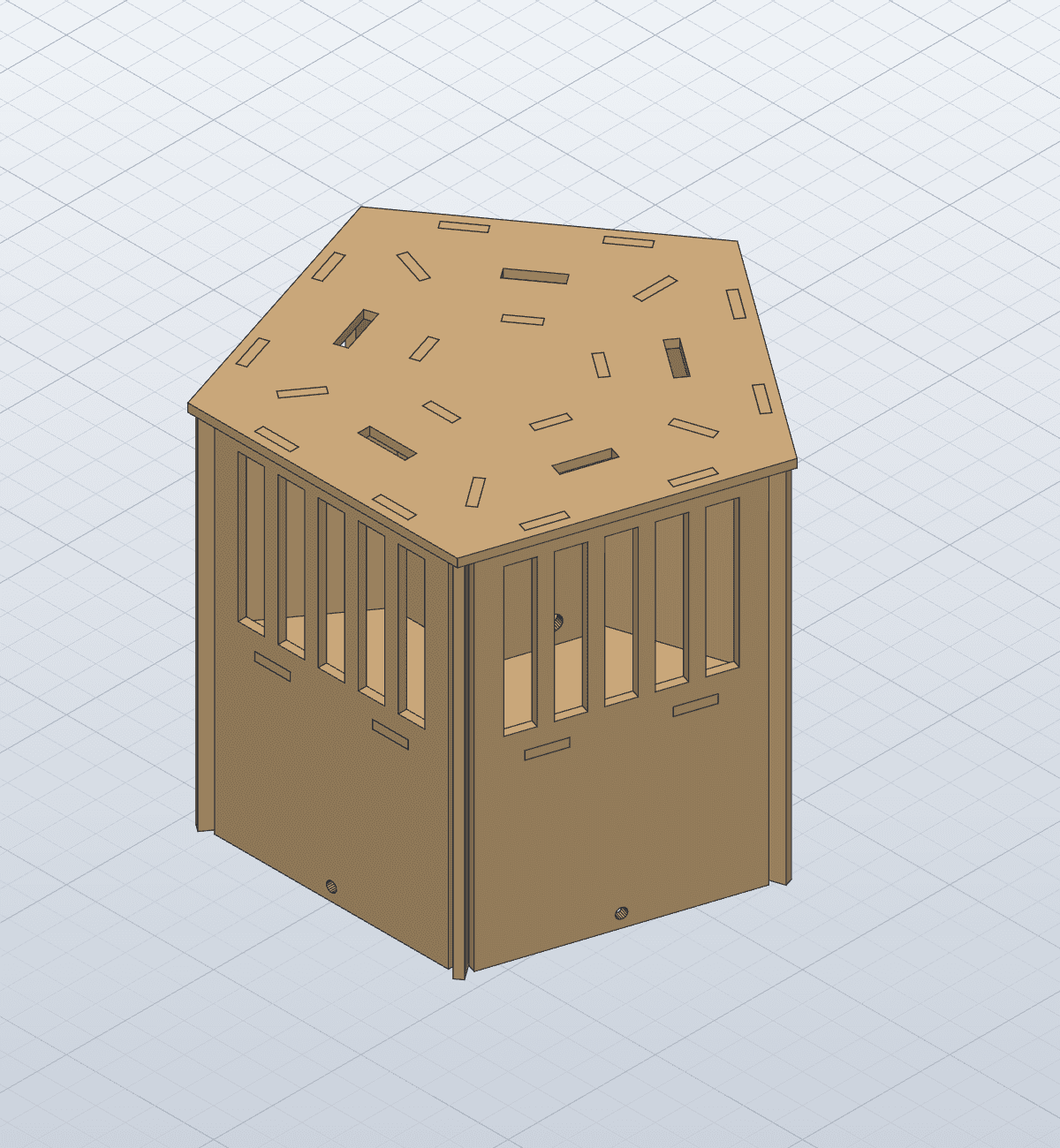
Laser-Cut 3S Servo Tester with ESP32-C3 and OLED
Build a battery-powered tester for up to six hobby servos, with an OLED, a rotary knob and a charging socket, all in an engraved plywood case cut from one 300 x 300 mm sheet.
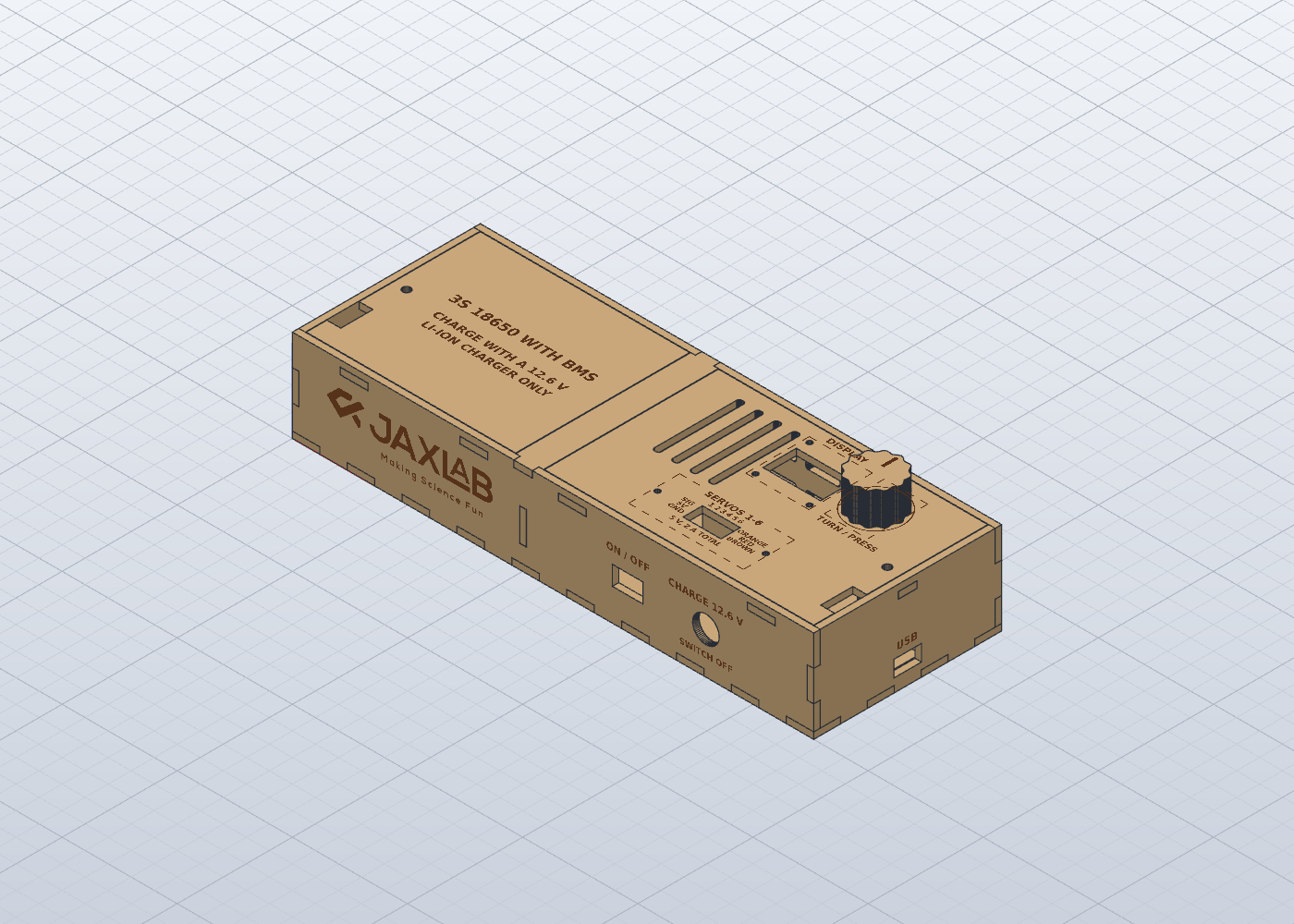
Project Overview
A complete bench tool for testing hobby servos, housed in a laser-cut wooden case. Tick any mix of six servos on the OLED, then move them by hand with the knob or let them swing automatically. A 3S 18650 pack with a BMS stays inside and charges through a socket on the front.
Follow the steps in order. Glue is hard to undo, so dry-fit before you glue.
This design has not been build-tested yet
The sizes and fit have been checked by calculation, but no one has built this case yet. Part sizes are typical values, not measurements of your parts. Check them below and cut the fit test before the full sheet. The firmware compiles, but hasn't yet been run on real hardware.
Stay safe
This project combines a laser, a hot glue gun, a soldering iron and lithium cells. Take each one seriously.
- Laser: never leave it running. Wear the correct safety glasses for your laser, and keep the room ventilated, because burning wood and glue give off smoke.
- Fire: keep an extinguisher close. Stop the job if flames keep burning between passes.
- Hot glue and soldering: both cause burns. Use a stand, and put the tools down between joints.
- Young builders should work with an adult, especially for the laser, soldering and cells.
- Cells: use matching 18650 cells from the same batch, and charge each to the same voltage before first connecting them.
- Short circuits: tape over bare wire ends, and take off rings and watches. A shorted 18650 can melt wire or start a fire.
- Charging: use a 12.6 V 3S Li-ion charger only, never a plain 12 V adapter. Stay nearby, and unplug it when it finishes.
- Wood burns: this case won't contain a cell fire. Don't leave it switched on or charging unattended, and keep it away from heat.
At a glance
| Specification | Value |
|---|---|
| Size | 226 mm wide, 82 mm deep, 40 mm tall |
| Weight (calculated) | About 118 g of wood, about 262 g with the cells, before the electronics |
| Wood | 36 parts on one 300 x 300 mm sheet of 2.8 mm wood |
| Designed for | TwoTrees TTS-10 Pro laser |
| Laser time | About 63 minutes for the full sheet |
Downloads
| File | Use |
|---|---|
| Fit test G-code | Run this first, on scrap of at least 135 x 55 mm |
| Full job G-code | Engraves, then cuts, the whole sheet |
| Cut only and engrave only G-code | The two stages separately |
| Cut paths SVG and DXF | For LightBurn or other CAM software, already kerf-compensated (0.12 mm) |
| Engraving raster PNG | 254 dpi, full bed |
| Fit test SVG | Fit test for other laser software |
| 3D model STEP | The case in CAD |
| Arduino sketch | Firmware for the ESP32-C3 |
Check your parts first
The case is sized for these typical parts. Sellers vary, so measure yours before you cut.
| Part | Sized for |
|---|---|
| Long nut, in each nut block | Round, 4.7 mm across x 11.3 mm long. M3 thread is assumed, so test it with your screw |
| 3S 18650 pack or holder | 78 x 63 x 24 mm |
| 3S BMS | 50 x 22 x 4 mm, rated for at least 10 A |
| DC charging socket | 11.3 mm across, in an 11.5 mm hole, up to 15 mm behind the wall |
| LM2596 module (2) | 43.5 x 22 x 14 mm |
| ESP32-C3 SuperMini | 22.5 x 18 mm, wires soldered on, no pins underneath |
| 0.96 inch I2C OLED | 27.5 mm board, 25 x 14.5 mm window, M2 holes 23.5 mm apart |
| Rotary encoder (KY-040 type) | 19 x 26 mm board, 7 mm threaded bush, 6 mm D shaft, 4.5 mm across the flat |
| Servo header pins | 6 x 3 straight pins, 2.54 mm pitch, on perfboard up to 50 x 22 mm |
| Rocker switch | 13.1 x 8.1 mm body in a 13.3 x 8.3 mm cut-out, up to 20 mm deep |
| Inline fuse holder | 14 x 50 x 10 mm |
Tools
- TwoTrees TTS-10 Pro laser and safety glasses
- Hot glue gun and thin glue sticks
- Soldering iron and solder
- Multimeter, which you'll need to set the 5 V
- Small screwdrivers, side cutters, wire strippers
- Calipers, to measure parts
- Fine sandpaper, for burnt edges
- A square, or any true 90 degree corner
- Computer with the Arduino IDE, and a USB-C cable
Did you know?
A multimeter is the most important safety tool here. An LM2596 can put out almost the full battery voltage until you adjust it, and that's enough to destroy a servo or the ESP32-C3.
How the parts join
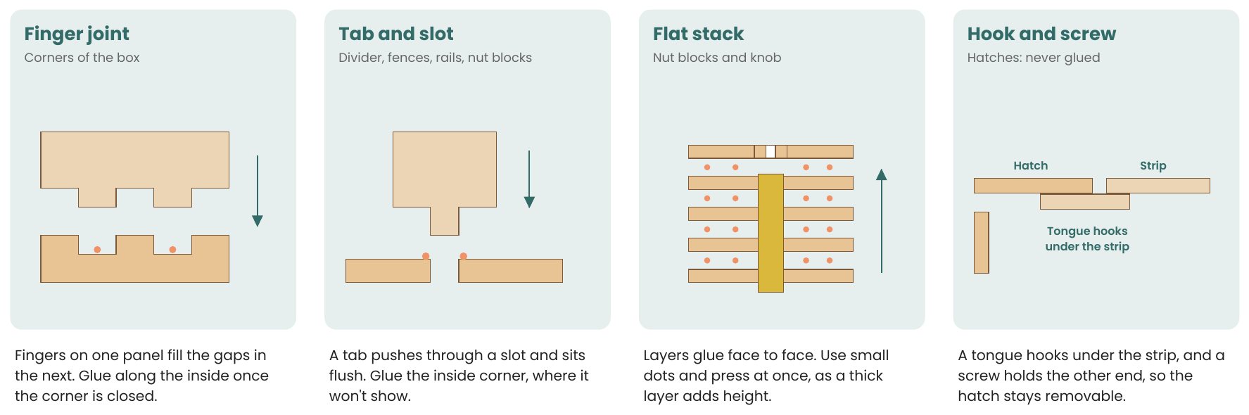
The case uses four kinds of joint. Laser-cut joints line themselves up, and the glue only has to hold them there. Orange dots in the picture show where the glue goes.
| Joint | Where it's used | When |
|---|---|---|
| Finger joints | Floor to all 4 walls, and the 4 upright corners | Steps 6 to 8 |
| Tabs and slots | Divider (4 tabs), 4 fences (2 tabs each), holder stop (1), 4 rails (2 tabs each), 2 nut tops (1 each) | Steps 5 to 8 |
| Tabs in notches | Strip: 2 tabs drop into notches at the top of the front and back walls | Step 9 |
| Flat stacks | 2 nut blocks (5 layers each), knob (5 layers), riser on the floor, tongue under each hatch | Steps 4, 5, 10, 11 |
| Hook and screw | Both hatches, with an M3 screw into each long nut | Step 18 |
Gluing with hot glue
Hot glue sets in seconds, so you get one chance at each joint. These habits prevent most mistakes.
- Dry-fit the whole case first, with no glue. Check that every tab seats and that you know which way each part faces.
- Engraving faces the right way: walls and hatches face outwards. The floor's engraving faces up, inside the case.
- Glue one joint at a time, starting with parts that are already in position.
- Run a thin bead along the inside of a tab or corner joint, so it stays out of sight.
- Use small dots on flat faces and press them together at once. A thick layer changes the height.
- Check the case is square before the last joints set. Use a square or a true corner.
Keep glue away from:
- The holder and module outlines on the floor, because the parts sit flat on foam tape there.
- Slots, until the part is in. Cold glue in a slot stops the tab from seating.
- The top faces of the rails, where the hatches rest.
- The nut's thread and the knob's D-shaped holes.
- The LM2596 modules. Hot glue softens when warm, so the modules stay on foam tape.
- Terminals and solder joints.
Made a mistake?
Warm the joint gently with a hot-air tool or the side of the glue gun's nozzle, and ease it apart once the glue softens. Peel off the old glue before trying again, and don't force cold joints, because 2.8 mm wood can split.
🛒 Materials Needed
- 300 x 300 mm sheet of 2.8 mm wood
- 3 matching 18650 cells with a 3S holder or pack
- 3S BMS, rated for at least 10 A
- 2 LM2596 buck converter modules
- ESP32-C3 SuperMini
- 0.96 inch I2C OLED display
- Rotary encoder (KY-040 type)
- Rocker switch
- DC charging socket
- Inline fuse holder, with a fuse to suit your wire and BMS
- 2 M3 x 10 screws and 2 long nuts, for the hatches
- 4 M2 x 8 screws and nuts, for the OLED, plus spacers if needed
- 2 M2 x 8 screws and nuts, for the header board
- Perfboard and 18 straight header pins
- 2 capacitors, 470-1000 uF, 10 V or more
- 1 Schottky diode, such as a 1N5819
- Foam tape, about 1 mm thick
- 1 small cable tie
- Servo-safe wire, solder, heat-shrink or tape
- 12.6 V 3S Li-ion charger, 1-2 A, centre-positive
📋 Step-by-Step Instructions
Test the fit on scrap first, so a bad fit costs a few minutes rather than a whole sheet.
- Use a scrap of at least 135 x 55 mm and run the fit test G-code. It takes about 5 minutes of cutting.
- Try every opening with the real part: a tab in the narrow slot, the long nut in the round pocket, an M3 screw, the switch, OLED glass, encoder bush, encoder shaft, header pins, charging socket and a USB plug.
- If something is too tight or loose, adjust the cut files for your part, then test again before cutting the full sheet.
| Laser setting | Value |
|---|---|
| Cut | 300 mm/min, 100% power (S1000), 2 passes |
| Engrave | 3000 mm/min, 25% power (S250), 0.1 mm line spacing |
| Air assist | Not switched on by the file |
| Focus | Set it by hand for your wood, as the file has no Z moves |
Machine settings to check
S1000 only means 100% if $30=1000 on your machine. M4 laser mode also needs $32=1.
Check the cut width
These parts allow for a 0.12 mm cut width. A wider cut can loosen joints. If tabs are loose in the fit test, the cut files need a larger allowance for your laser.
All 21 steps completed — great work!